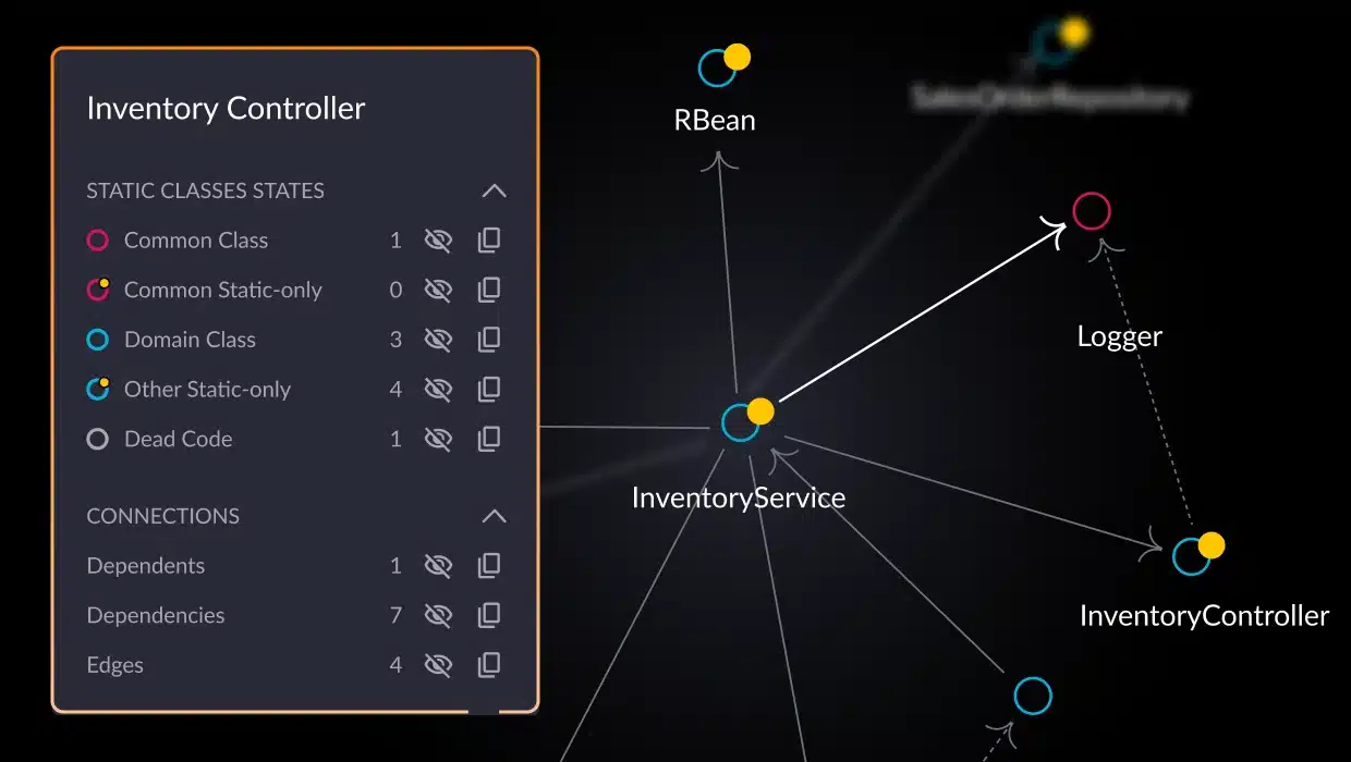
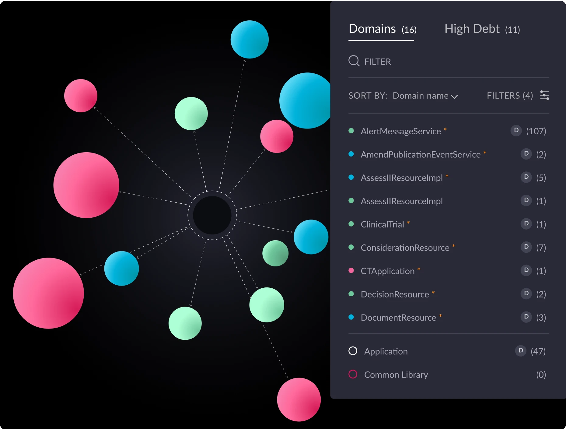
Explaining a complex software system to your team or stakeholders can be challenging, especially in fast-paced agile environments where systems evolve rapidly and during cloud migrations when change is constant. Architecture diagrams give a clear way to represent system structures, relationships, and interactions, making it easier to understand, monitor architectural drift, and communicate your ideas. The right tools keep the diagram in sync with the implementation, fostering alignment across teams even in the midst of rapid releases and dynamic microservices architectures.
Capturing the actual architecture is essential before cloud migration to identify the best path for modernization. It remains just as important afterward, in a microservices world, to prevent drift and the return of architectural technical debt.
In this guide, we’ll explore the importance of software architecture diagrams, outline common types, and offer practical advice to create diagrams that enhance collaboration and decision-making even as evolving functionality reshapes existing architecture. Whether troubleshooting a legacy system or designing something new, you’ll walk away with actionable insights to communicate your ideas effectively and keep your entire team aligned and informed.
What is an architecture diagram?
An architecture diagram is a blueprint of a software system, showcasing its core components, their interconnections, and the communication channels that drive functionality. Unlike flowcharts that describe behavioral control flows, architecture diagrams capture the structural aspects of the system, including modules, databases, services, and external integrations. This comprehensive overview enables developers, architects, and stakeholders to grasp the system’s organization, identify dependencies, and foresee potential challenges. Because architecture diagrams provide a clear snapshot of the system’s design, they are essential tools for planning, development, and ongoing cloud maintenance. Modern approaches emphasize structural aspects, because the core architecture of a system tends to evolve gradually, providing a stable foundation, while the behavior of individual components and their interactions are constantly changing as new features and updates are introduced.
Key features and purpose
Architecture diagrams show how a software system is structured by focusing on key elements like components, connectors, and relationships.
- Components: These represent the system’s fundamental building blocks, such as individual modules, databases, services, and external systems. For instance, in a web application, components include mobile and web based clients, authentication service, load balancers, and database engines.
- Relationships: These define how components are related and interact with each other at the logical level. Architecture diagrams help establish relationships between components, making it easier to identify dependencies and communication pathways. For example, a mobile client app may use an identity provider service for single sign-on using an SDK. Understanding these relationships helps identify dependencies and potential bottlenecks within the system.
- Connectors: These depict the messaging interactions and data flow channels between components. Connectors can show various communication protocols, such as HTTP requests between a front-end application and an API server or database connections between an application and its database.
Architecture diagrams are visual tools that help explain the structure of a system, making it easier for stakeholders to understand how everything fits together. They break down complex systems at varying abstraction levels, making the information more accessible to people with different levels of technical knowledge. These diagrams are important documentation and a reference for building and maintaining the system over time. They also play a key role in decision-making because they provide a clear view of the system’s design, which can be helpful when it comes to planning for scalability, performance, and other technical details. Architecture diagrams are invaluable for troubleshooting because they help identify potential issues or bottlenecks.
During the planning phase, they guide the design process, offering a roadmap for scalability and modularity. They also ensure the system meets security and regulatory standards by showing how data moves and where sensitive information is stored or processed.
Why architecture diagrams matter in system design
Modern software systems are increasingly complex, often involving many components, services, and integrations. While advanced tools such as Microsoft Copilot, Sonarqube/cloud, APMs and others are valuable to ensure code quality and performance, they don’t replace the need to visually represent the system’s architecture.
Keeping diagrams updated to accurately reflect the system’s architecture is essential for risk mitigation and effective communication throughout development.
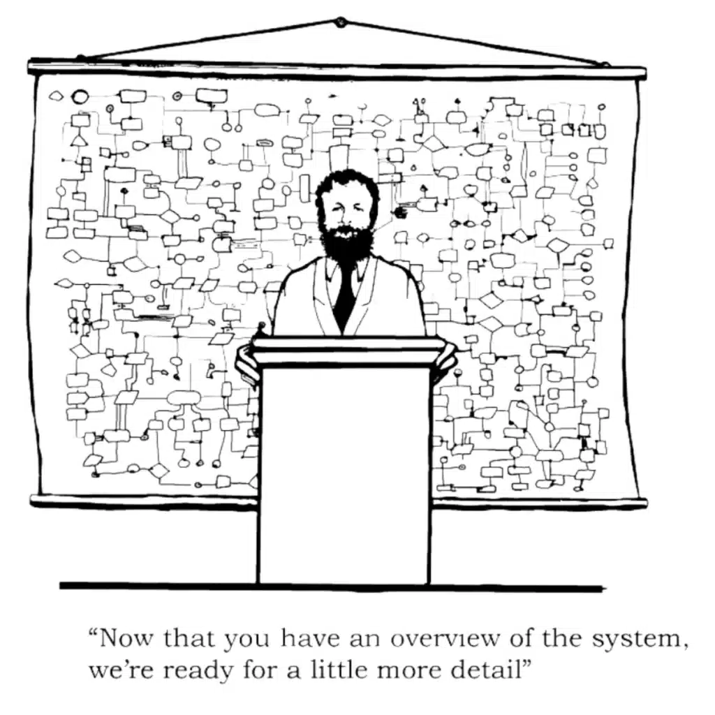
The importance of visual system design includes the following key aspects:
Enabling informed decision-making
A comprehensive architecture diagram allows developers and architects to understand the overarching system at a glance. For example, when deciding between a microservices architecture and a monolithic design, a detailed diagram can highlight how services interact, helping stakeholders assess scalability, maintainability, and deployment implications.
Accelerating development time
With a clear architectural blueprint, development teams can work more efficiently. The diagram is a reference point that reduces ambiguity, aligns team members on system components, and streamlines the development process. This clarity minimizes misunderstandings and rework, thereby shortening development cycles.
Enhancing system maintainability
Maintenance and updates are inevitable in software development. Architecture diagrams make it easier to identify which components may be affected by a change. For instance, if a particular service needs an update, the diagram can help determine its dependencies, ensuring that modifications do not inadvertently disrupt other parts of the system.
At the end of the day, architecture diagrams are more than just visual aids; they facilitate better design, efficient development, cloud migration and modernization strategy, and smoother maintenance of the systems they describe. By clearly depicting the system, they help teams navigate complexities and collaborate effectively to build robust software solutions.
Common types of architecture diagrams
No single architecture diagram can capture every aspect of a system’s complexity. Different types of architectural diagrams are intended to highlight a viewpoint about the system’s components, interactions, and perspectives. Below are some of the most common types of architecture diagrams and their unique applications.
Architecture diagrams in UML
Unified Modeling Language (UML), defined by the Object Management Group (OMG), remains one of the most widely used modeling standards in software engineering. It is a staple in software engineering education, supported by numerous tools, and many methodologies have adopted a subset of its diagrams, making it a versatile choice for system design. Some of the tools are open source (like PlantUML) and some are commercial tools (like MagicDraw and Rhapsody) with advanced capabilities like code generation, simulation and formal verification of models.
Of UML’s 14 diagram types, class and object diagrams are among the most commonly used, often combined into a single diagram to describe architecture at different abstraction levels. These diagrams define relationships between classes and objects, such as association, aggregation, composition, inheritance, realization, and dependency, which can be further customized using UML profiling extensions. UML class diagrams are commonly used to define data models, representing how data is organized and related within the system. While UML allows for semantically precise specifications, it can also introduce complexity or potential over-specification, potentially causing confusion among stakeholders.
Here is an example UML class diagram along with an explanation of its various elements.
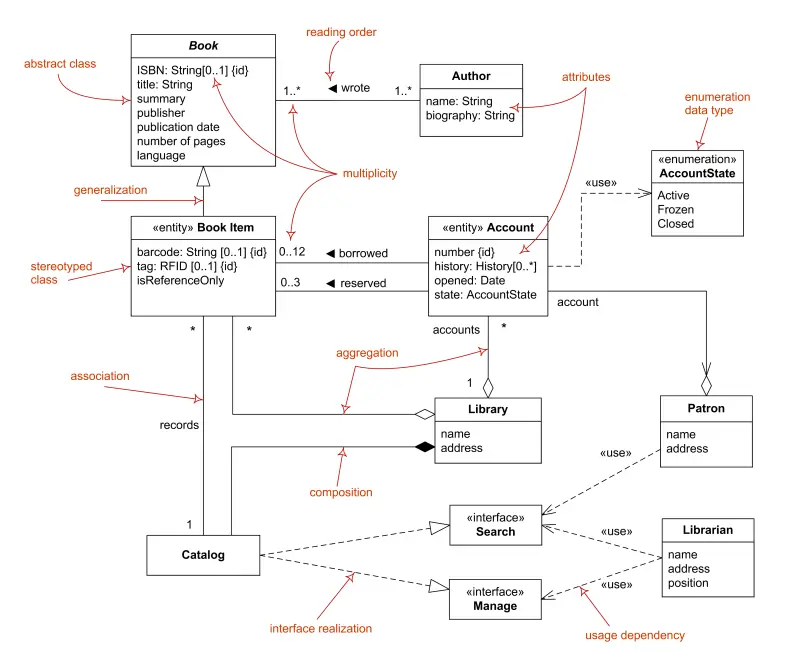
Source: https://www.uml-diagrams.org/class-diagrams-overview.html
And here is an example object diagram from the same source:
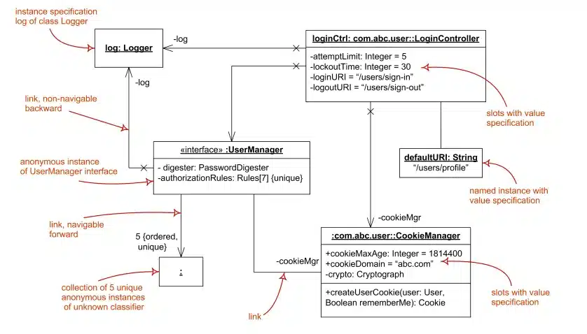
While developers use component and deployment diagrams less frequently in UML, these diagrams play a crucial role in showcasing high-level architectural elements. The following is an example of a deployment diagram:
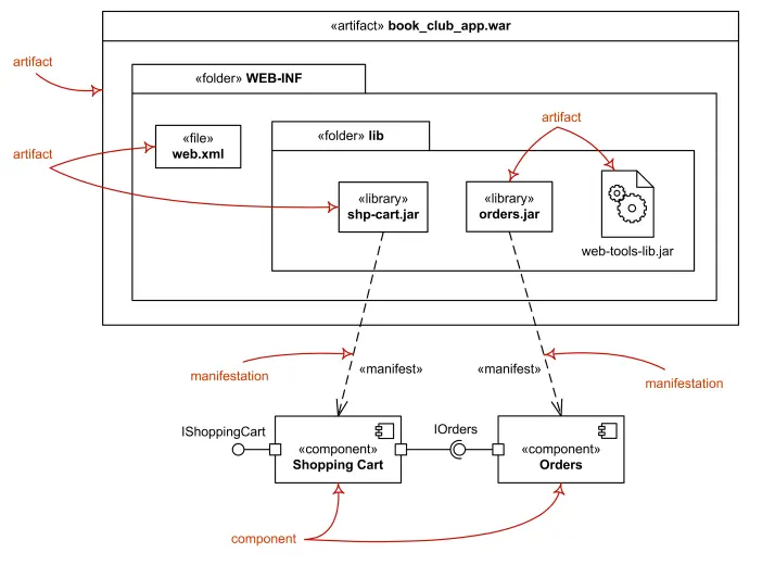
In summary, UML architectural diagrams are among the most expressive and detailed tools for conveying complex system designs. They are best suited for technical stakeholders, such as architects conducting deep-dive reviews or developers optimizing an architecture based on detailed requirements. However, effectively using UML requires a solid understanding of the language and a well-defined methodology, contributing to its declining adoption.
C4 model
The C4 model, created by Simon Brown between 2006 and 2011, builds on the foundations of UML as a lean, informal approach to visually describe software architecture. Its simplicity and practicality have made it increasingly popular since the late 2010s.
Unlike UML, the C4 model focuses on the foundational building blocks of a system — its structure — by organizing them into four hierarchical levels of abstraction: context, containers, components, and code. This organization provides a clear, intuitive way to understand and communicate architectural designs. Some of the UML tools, like PlantUML, also support C4 diagrams, but C4 is still not as widely accepted as UML and has less tool support overall.
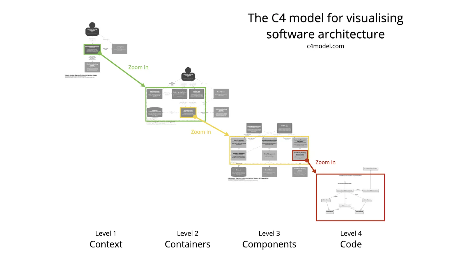
This context diagram (shown at the highest level of abstraction) represents an Internet Banking System along with its roles and the external systems with which it interacts.

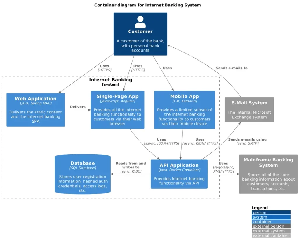
This container diagram “zooms in” on the Internet Banking System from the context diagram above. In C4, a container represents a runnable or deployable unit, such as an application, database, or filesystem. These diagrams show how the system assigns capabilities and responsibilities to containers, details key technology choices, maps dependencies, and outlines communication channels within the system and with external entities like users or other systems.
Below is a component diagram that zooms in on the API application container from the above container diagram. This diagram reveals the internal structure of the container, detailing its components, the functionality it provides and requires, its internal and external relationships, and the implementation technologies used.
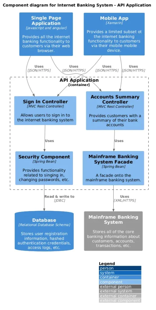
C4 introduces a clear and intuitive hierarchy, where container, component, and code diagrams provide progressively detailed “zoom-in” views of entities at higher abstraction levels. This structure offers a straightforward and effective way to design and communicate architecture.
In summary, C4 offers standardized, tool- and method-independent views, making it versatile for communicating designs to various stakeholders. However, it lacks the level of detail and richness that UML provides for intricate specifications.
Architectural diagrams for designing cloud solutions
Cloud vendors like AWS, Azure, and Google provide tools for creating architecture diagrams to design and communicate solutions deployed on their platforms. These diagrams often use iconography to represent various cloud services and arrows to illustrate communication paths or data flows. They typically detail networking elements such as subnets, VPCs, routers, and gateways since these are crucial for cloud architecture. Additionally, cloud architecture diagrams often illustrate the physical layout of hardware and software resources to optimize deployment and communication between components.
Here is an example diagram from AWS:
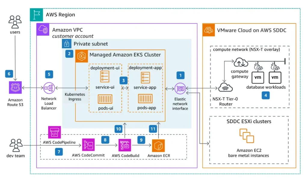
A typical pattern which is shown in the above diagram is to add numbered labels on the lines (as shown above) and have a list describing a main interaction across the components (as shown here)
Free drawing tools such as https://app.diagrams.net/ enable drawing these diagrams by having the icons of the various cloud services out of the box. Other more cloud-specific commercial tools like Cloudcraft and Hava.io offer various automations such as diagram synthesis from an existing cloud deployment, operational costs calculation and more.
It is nearly impossible to design and communicate cloud solutions without visualizing the architecture. Unlike UML and C4, cloud architecture diagrams focus on the deployment of cloud services within the cloud infrastructure, illustrating their configuration, interactions, and usage in the system.
System and application architecture diagrams
Other widely used diagrams include system architecture and application architecture diagrams. System architecture diagrams provide a high-level overview of an entire system, showcasing its components—hardware, software, databases, and network configurations—and their interactions. In contrast, application architecture diagrams focus on a specific application within the system, highlighting internal elements such as the user interface, business logic, and integrations with databases or external services. These diagrams offer stakeholders valuable insights into the overall system structure, operational flow, and application-specific details.
Benefits of using architecture diagrams
Architecture diagrams are essential tools that bring significant value throughout the software development lifecycle. By providing a clear visual representation of system components, interactions, and dependencies, they help streamline communication, identify risks early, and support informed decision-making. Here are some of the key benefits:
Enhancing collaboration and communication
Architecture diagrams are a visual tool that connects technical and non-technical stakeholders. By illustrating the system’s structure and components, they help everyone—developers, designers, project managers, and clients—understand how the system works. This clarity reduces misunderstandings and ensures that everyone stays aligned throughout the development process.
Risk mitigation and issue identification
Visualizing the system’s architecture early in the process makes identifying potential risks, bottlenecks, and design flaws easier. Spotting these issues upfront allows developers to address them proactively, preventing problems from escalating during development or after deployment. This leads to more reliable and robust systems.
Streamlining scalability and efficiency
Architecture diagrams help teams understand system dependencies and interactions, which is crucial for planning cloud migration, future scalability, and maintaining efficiency. By visualizing how components interact, developers can make well-informed decisions about scaling, optimizing performance, and planning for growth.
In short, architecture diagrams play a crucial role in creating better software by improving communication, minimizing risks, and supporting scalability and efficiency. By integrating them into your development process, you can build systems that are more reliable, maintainable, and better equipped to grow with your business and meet the evolving needs of your users.
Challenges with traditional architecture diagrams
While architecture diagrams are vital tools for planning and communication, they often face a significant challenge: keeping up with the pace of modern software development. Diagrams are typically created during the initial design and development stages when teams map out how they expect the system to function. However, as the software evolves—through updates, new features, and shifting requirements—the reality of the system’s architecture can drift far from the original design.
This “architectural drift“ occurs because manual updates to diagrams are time-consuming, easily deprioritized, and prone to oversight. The result is a disconnect: diagrams remain static artifacts while the software grows more dynamic and complex. Teams are left relying on outdated visuals that fail to reflect the actual architecture, making it harder to troubleshoot issues, onboard new developers, or plan for scalability.
This challenge is especially acute after cloud migration and modernization. As organizations modernize applications—often transforming monoliths into microservices—they gain development velocity. But without capturing and monitoring the architecture, that speed can quickly accelerate architectural drift.
In the early 2000s, some UML modeling tools, like IBM Rhapsody, attempted to tackle this challenge with features like code generation (turning models into code) and round-tripping (syncing code back into models). They even integrated these modeling capabilities into popular integrated development environments (IDE) like Eclipse, allowing developers to work on both models and code as sort of different views in a single environment. However, this approach didn’t catch on. Many developers found the auto-generated code unsatisfactory and opted to write their own code using various frameworks and tech stacks. As a result, the diagrams quickly became irrelevant.
Bridging the gap: The need for dynamic, real-time architecture
Modern tools and practices must move beyond static representations to deliver value and real-time architectural insights. Automated solutions can continuously monitor and visualize system components and interactions as they change, ensuring diagrams stay accurate and actionable. Tools such as vFunction automatically document your live application architecture, before cloud migration and post modernization, generating up-to-date visualizations that reflect the actual system and its runtime interactions, not just the idealized design. By ensuring architecture diagrams keep pace with the working system, teams can make informed decisions, uncover hidden dependencies, and confidently manage complexity as their software evolves post modernization.
DevOps and integration: The evolving role of architecture diagrams
As software development evolves with the rise of DevOps practices and microservices architecture, the role of architecture diagrams has expanded to meet new challenges. DevOps architecture diagrams are now vital for visualizing the components of a DevOps system and illustrating how these components interact throughout the entire pipeline—from code integration to deployment. These diagrams help development teams understand the flow of processes, pinpoint areas for automation, and ensure that the devops system operates smoothly and efficiently.
Integration architecture diagrams, meanwhile, focus on how different components interact with each other and with external systems. By highlighting the protocols and methods used for integration, these diagrams make it easier to identify potential issues, streamline communication, and ensure seamless data flow across the system. In environments built on microservices architecture, integration architecture diagrams are especially valuable for mapping out the complex web of service interactions and dependencies.
Architecture diagrams provide a common language for development teams, stakeholders, and even external partners, ensuring that everyone has a shared understanding of how the system works. By visually representing how components interact, these diagrams facilitate collaboration, reduce misunderstandings, and help teams build more resilient and adaptable software systems.
Step-by-step guidelines for creating and using architecture diagrams
Architecture diagrams, including the above mentioned types, cannot be formally validated (except in some advanced UML cases with specialized tools). To avoid confusion, follow a systematic approach when creating and using these diagrams. For instance, inconsistencies or duplications between diagrams can lead to misunderstandings, as can ambiguous notations. Be cautious with elements like colors, which may not have a universally understood meaning, or arrows and lines that could be misinterpreted, such as representing data flows instead of dependencies. A clear and consistent approach ensures better communication and understanding among stakeholders.
Before we go into the step-by-step procedure, here are a few guidelines:
- Using standardized symbols and notations: Using standardized symbols and notations is a way to avoid misinterpretations. If you draw a cloud architecture, make sure to use the correct icons and labels by selecting them from a catalog. If you are using C4, make sure to follow the notation and use the right terminology, if you are using UML make sure to follow the standard and opt to use a tool that can check and enforce semantic correctness. This will also save lengthy explanations when presenting to stakeholders familiar with the language.
- Focusing on clarity and simplicity: Keeping your architecture diagrams clear and simple is essential for effective communication. It’s best to avoid too many details that can make the diagram confusing. Instead, focus on the key components and their interactions. For example, when mapping out a web application’s architecture, focus on the frontend, backend, database, and external APIs without including every minor module. Use concise, clear labels and consistent symbols to ensure everyone can easily understand the system’s structure. Deployment architecture diagrams should also clearly indicate deployment environments, such as development, staging, and production, to facilitate planning and optimization.
- Selecting the right diagram type and tool: As discussed earlier, each diagram type serves a specific purpose. Select the type that best suits your needs and the information you want to convey. Leverage diagramming tools with helpful features like automated layouts, version control, and collaboration options. These tools can make the diagramming process more efficient and improve the quality of your diagrams.
- Make the diagrams visually appealing: Aesthetic diagrams are easier to communicate and appeal more to stakeholders, in the same way that aesthetic presentations and documents are better received by stakeholders.
Here is a high-level step-by-step procedure to design an architecture of a new system:
Step 1: Choose the right tool and language according to your purpose
The stakeholders and purpose of the diagram should determine the language and tool used for the specification. For cloud architecture use tools that support the iconography and conventions of your cloud provider such as draw.io, lucidchart, etc. For high level architectural specification use one or more of the C4 diagrams, a list of available tools is specified here. For detailed technical specifications for technical stakeholders use UML, which has a wide set of tools. For a list of UML tools click see this Wikipedia page.
Step 2: Start from the system context and elaborate the internal structures
When specifying a new architecture, it is recommended to start the specification with the roles and external entities and the relationship with the system as a whole and then elaborate the subsystems and their components and then zoom in to the components internal structure. Capturing user interactions in architecture diagrams is important for understanding how user actions trigger events and system responses, especially in event-driven architectures. This is consistent with the C4 approach of context->containers->components->code, but the same holds for cloud architecture diagrams and UML diagrams.
If needed, include non-functional elements or resources that are key to the architecture such as subnets, protocols and databases.
Step 3: Verify the architecture with a few scenarios
Choose a few main scenarios and verify that the components and the relationships support them. This will also help in reviewing the architecture with others. You can do it at the system context level as well as at the detailed design level. A common technique to do this is to label the steps on top of the relationships and describe the interaction. Another way is to use UML sequence diagrams to describe the interactions across the components and ensure that every communication between lifelines has a supporting relation in the architecture. Sequence diagrams provide the means to include details such as alternative and parallels interactions, loops and more and are frequently used for detailed designs. Sequence Diagrams are useful in defining APIs as well as serving as a basis for the definition of unit, integration and system tests.
Step 4: Review, annotate and iterate
Once you have a baseline architecture, always review it with relevant stakeholders, add their comments on top of the diagrams and make the necessary refinements based on their feedback. Some tools have built in collaboration features that include versioning, annotations and more.
Creating an architecture diagram for an existing system
Designing architecture diagrams for new systems is straightforward, but understanding and communicating the architecture of an existing complex system—whether monolithic or distributed—can be significantly more challenging. Reverse-engineering code to create diagrams is difficult, especially in distributed applications with multiple languages and frameworks. Even tools like Enterprise Architect or SmartDraw often produce outputs that are overly complex and hard to interpret.
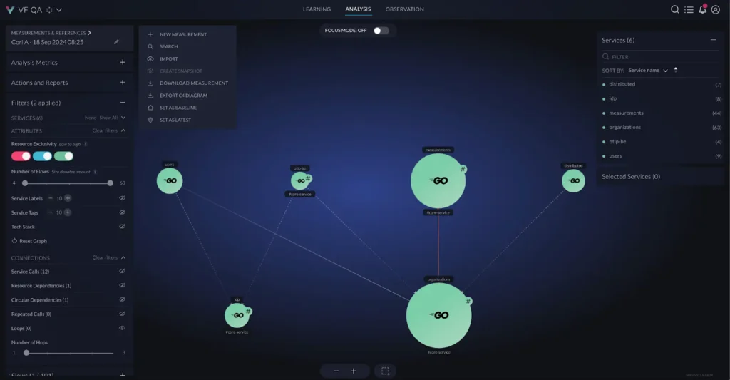
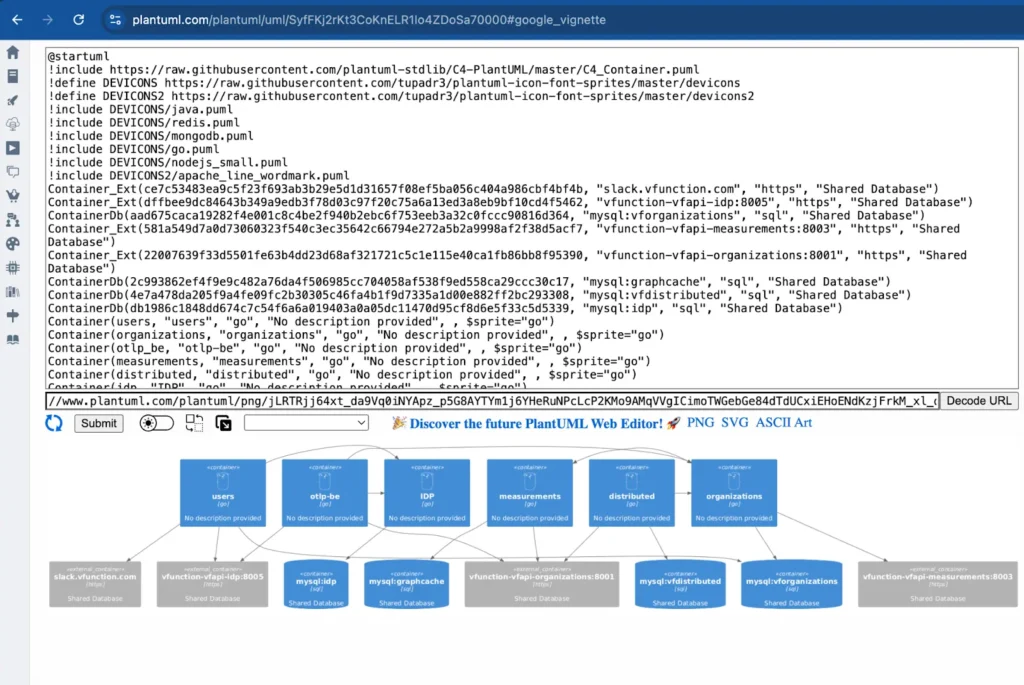
The C4 model simplifies software visualization with context, container, component, and code diagrams. Using OpenTelemetry, vFunction analyzes distributed architectures and allows teams to export live architecture into C4 container diagrams for visualization with tools like PlantUML. This approach helps engineers conceptualize, communicate, and manage architectures more effectively, especially in a post-modernization distributed environment.
vFunction can also import C4 container diagrams as a reference architecture and create TODO items (tasks) based on its analysis capabilities to bridge the gaps between the current architecture and the to-be architecture.
With its “architecture as code” capability, vFunction aligns live systems with C4 reference diagrams, detecting architectural drift and ensuring real-time flows match the intended design. It helps teams understand changes, maintain architectural integrity, and keep systems evolving cohesively in the cloud.
The critical role of architecture diagrams in software development
In software development, systems can become so complex that explaining ideas through words or traditional documentation often falls short. Architecture diagrams simplify this complexity, providing a clear and concise way to communicate intricate concepts, including your system’s structure, components, and interactions. For these diagrams to truly add value, they must break out of the ivory tower—evolving from static, theoretical artifacts into dynamic, living tools that accurately reflect the current state of your software on premise or in the cloud..
Keeping these diagrams accurate with minimal effort from developers allows them to integrate into day-to-day workflows seamlessly. This enables teams to foster collaboration, uncover hidden issues, and ensure systems evolve with clarity and purpose. You can build more efficient, maintainable, and scalable software by incorporating these diagrams into your development toolkit. To learn more about how vFunction helps keep architecture diagrams aligned with real-time applications, visit our architectural observability for microservices page or contact us.


